From Conputer-Controlled Cutting assignment page: characterize your lasercutter’s focus, power, speed, rate, kerf, joint clearance and types.
You can edit the README.md (this) file directly and add
images to the repository and integrate them with
[alt text](my-image.jpg) syntax.
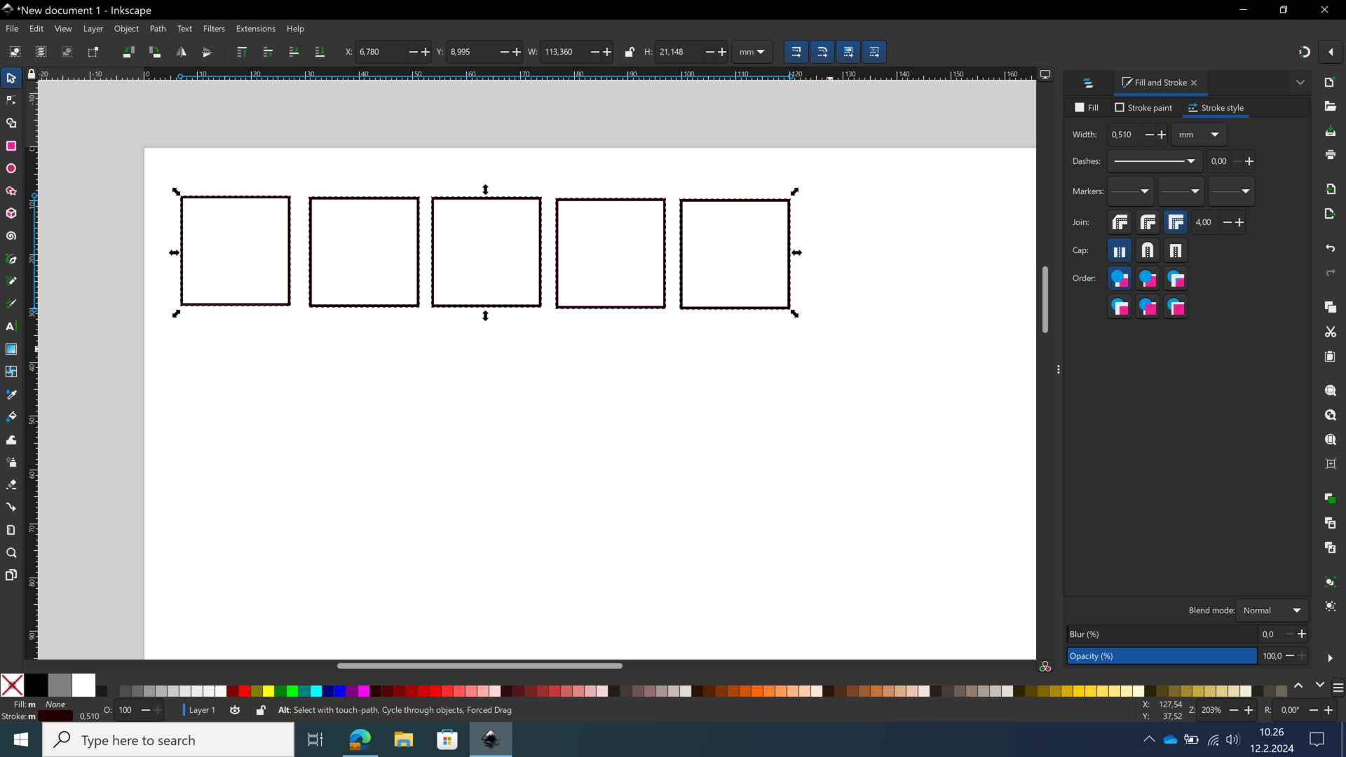
We chose 4mm birch plywood as the material for our tests for today. We first started out by measuring the kerf. For this, we created five 20mm squares in Inkscape. For these to register as cutting lines, we set the stroke to 0.01 mm and remove all fill.
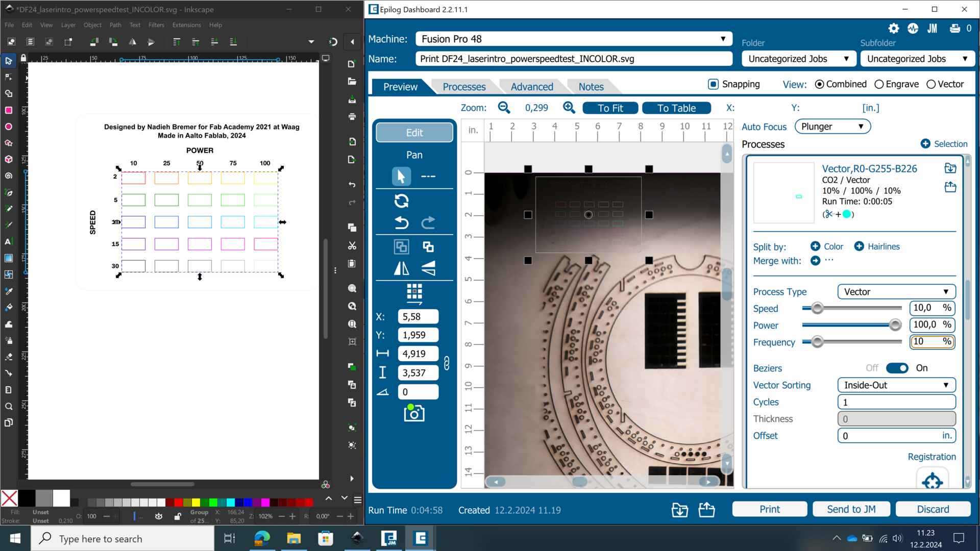
Once our design is ready, we print it straight out of Inkscape, making sure that “Epilog Engraver” is selected as the printer. The design is transferred to the Epilog Dashboard. From here, we can place our design on the material, and adjust the settings. For these cuts, we used the preset for 4mm plywood from our material library. The power, speed and frequency values can be seen below. In the later parts of the group assignment, we also changed these preset settings to test the optimal values.
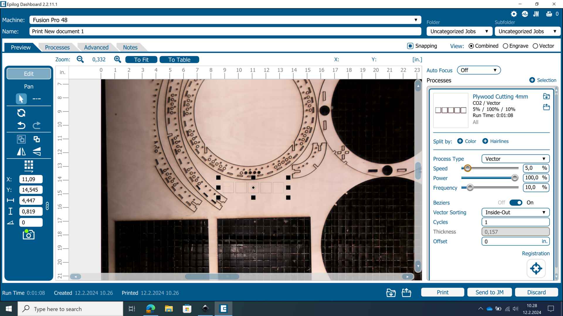
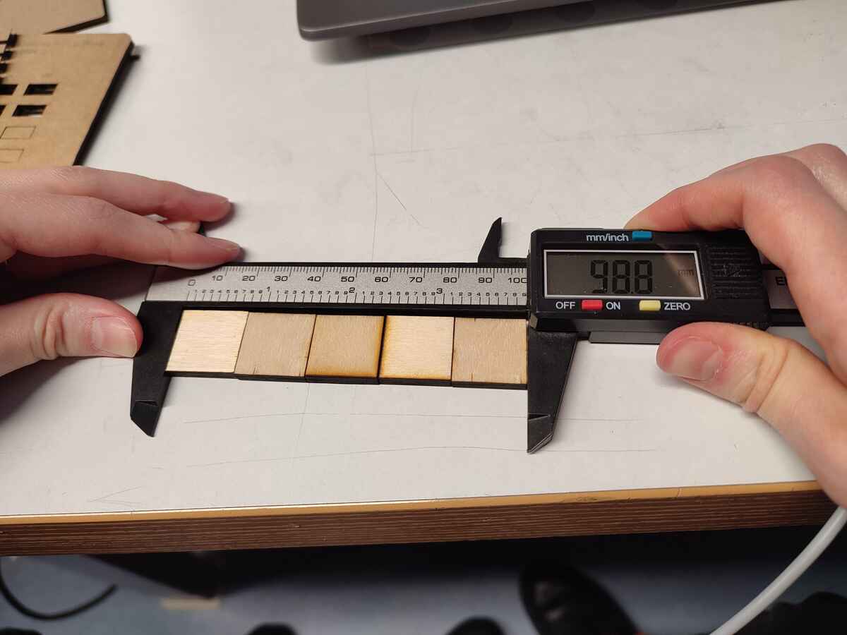
We started the cut and now we have our squares. To measure the kerf, we allign them side by side and measure the length. It is 98.8. Since it is supposed to be 100 mm, we have 1.2 mm of missing material. We divide 1.2 by 5, and find 0.24 as our kerf value. This is the width of the laser beam.
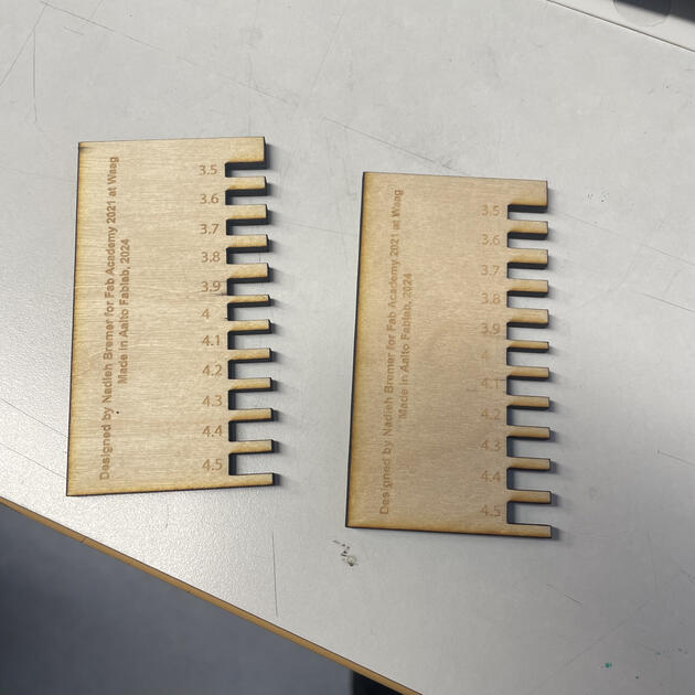
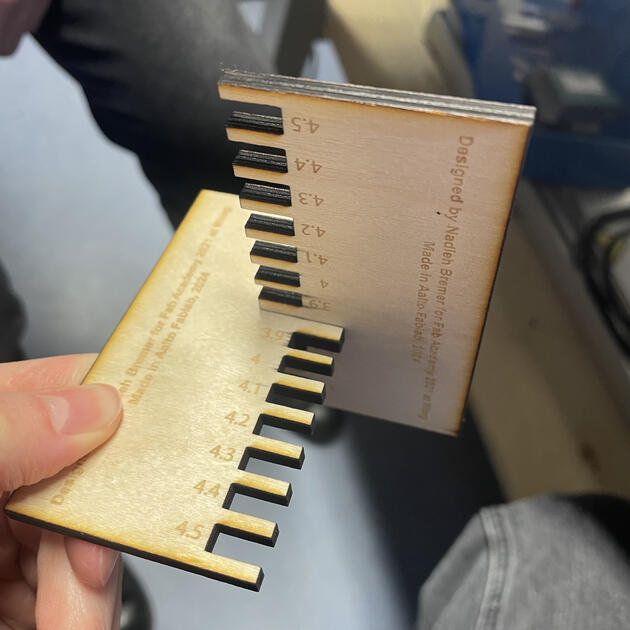
We also did a comb fitting test. We adapted Nadieh’s design to fit our 4mm plywood, by putting 4mm gap in the middle and incresing/ decreasing the values in 0.1 increments.
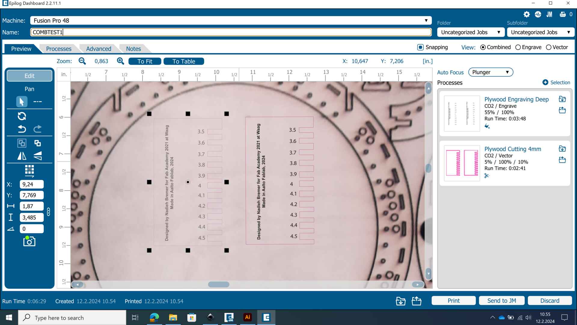
We place the design in Epilog Dashboard, and set up our engraving and cutting values with the presets again.
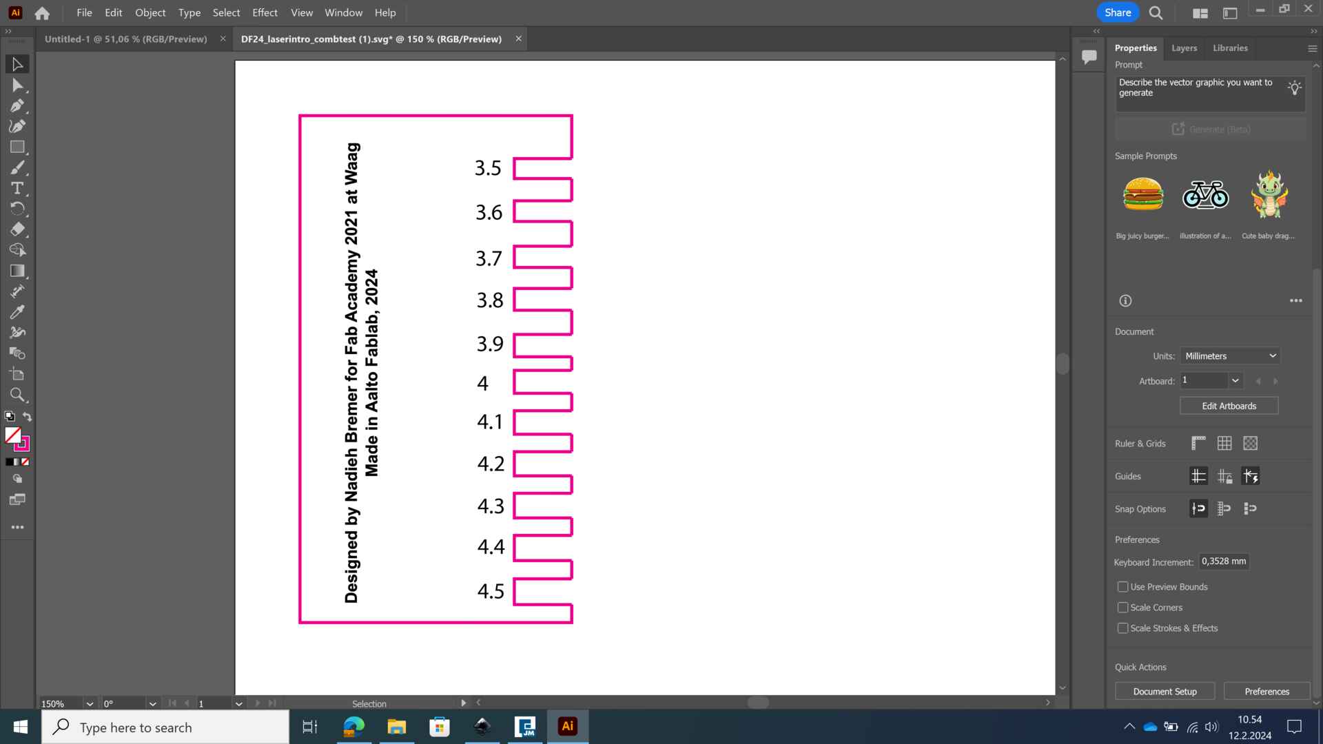
Below, you can see the final piece. The 3.8 mm gap seems to be the best for tight fitting. 3.9 would also be a good value if we want a looser fit.
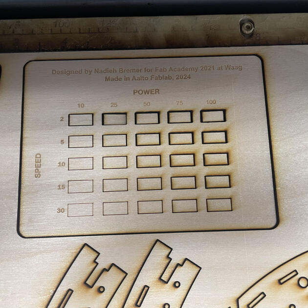
Finally, we moved on to the power vs speed test. Again, we modified Nadieh’s design to fit our needs. In Epilog Engraver, we are able to do “color mapping”. Which means we can split the design by color, and give different power/ speed/ frequency values or change the order the design is going to be cut in. So, we gave easy-to-distinguish colors to the different rectangles there were going to be cut.
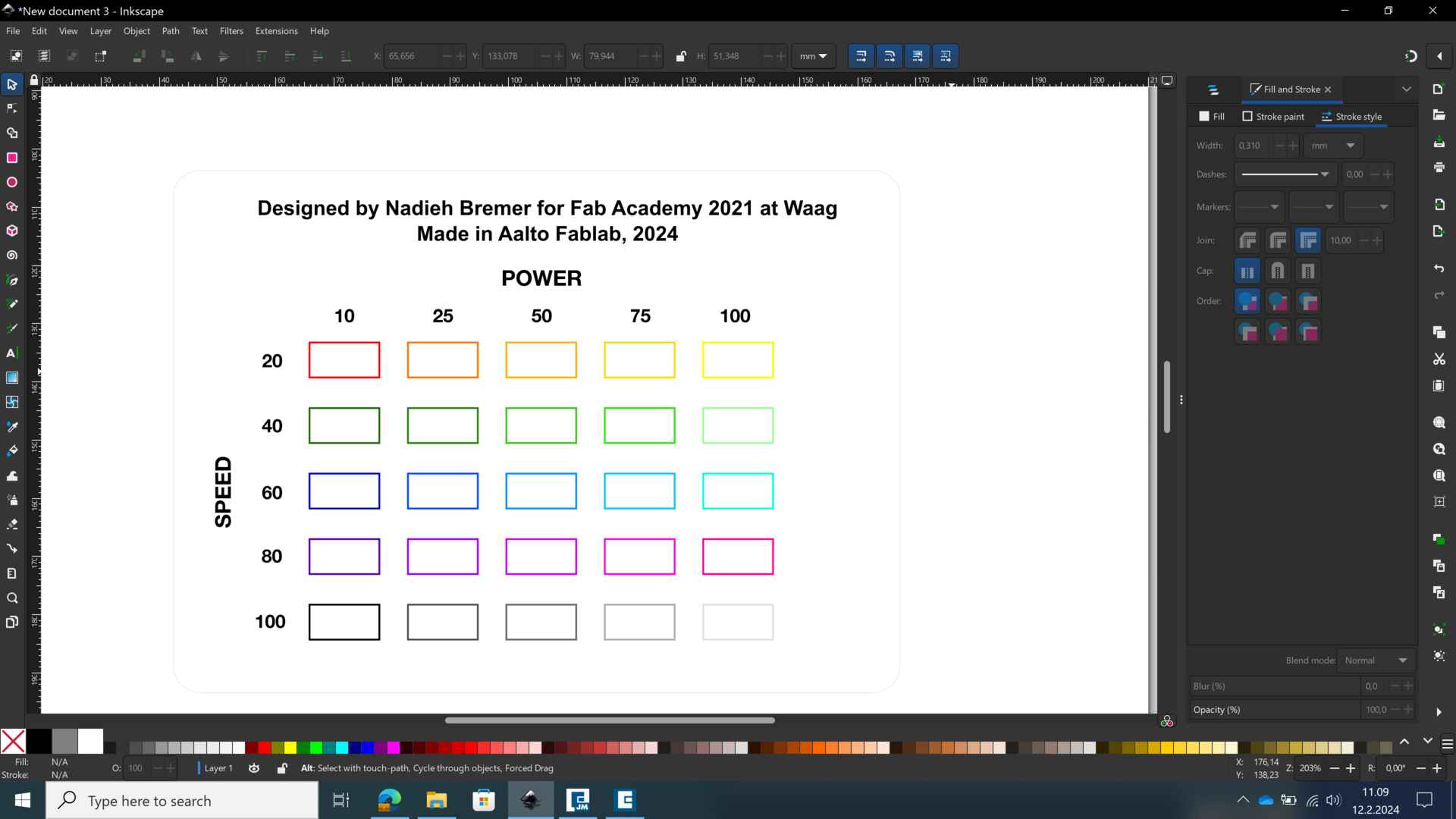
We also adjusted the speed settings from Nadieh’s design, since the lowest speed there was 20 and we were already having problems with cutting 4 mm plywood with 10 speed and 100 power. So we adjusted to scale to fit the material, as seen in the screenshot below.
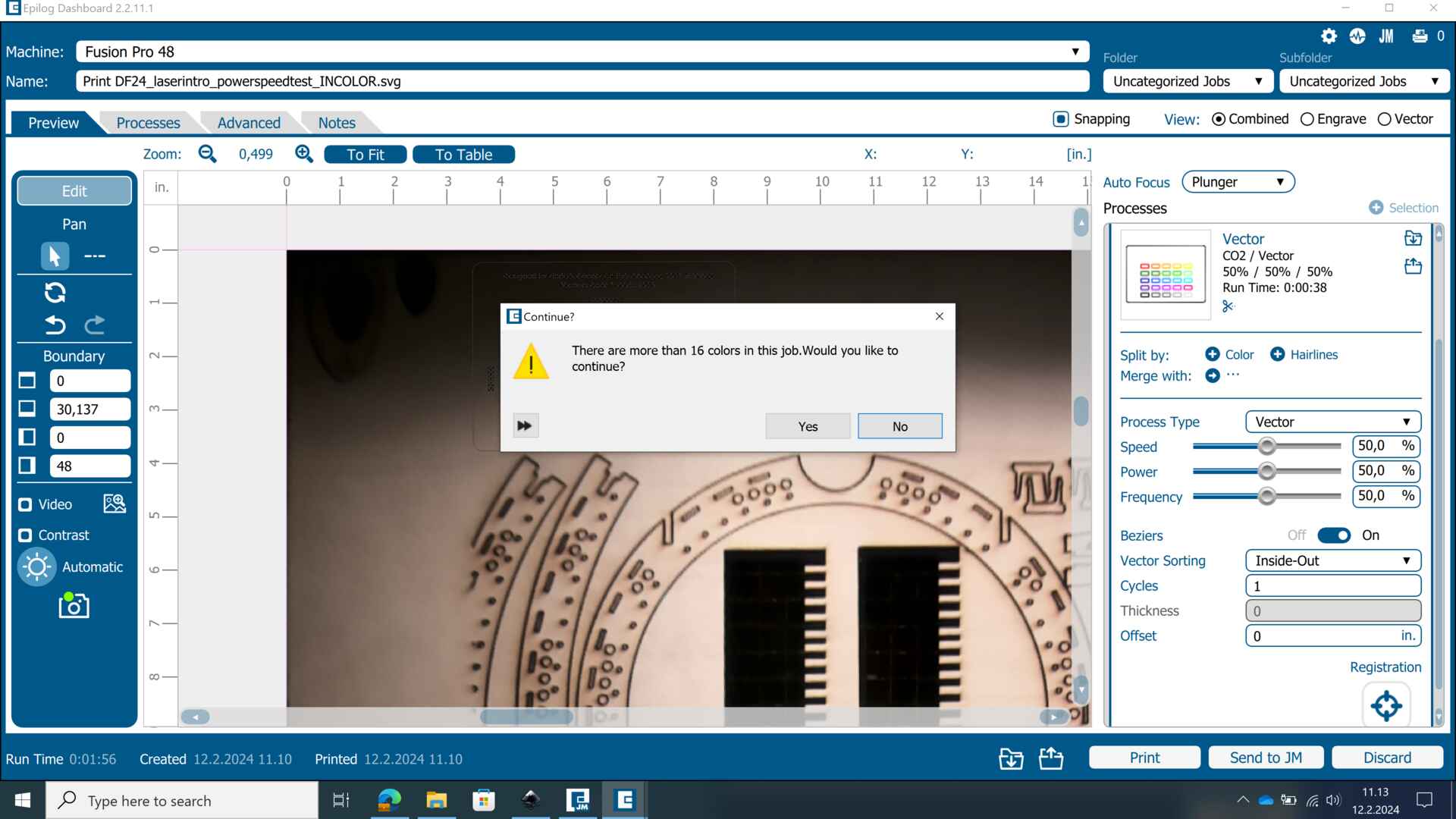
When we put the designs to Epilog Dashboard and try to split by color, it points out that we have too many colors. Yes, we do, and we want to continue. We then adjusted all the settings for the 25 different colors one by one.
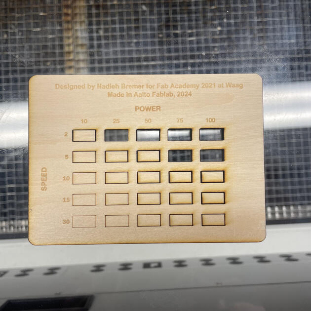
Finally, our power vs speed test was done. We found out that 75 power & 5 speed or 100 power & 5 speed (frequency 5 in all of them) were good combinations. They were optimal in the sense that the cut went all the way through, and there was the less burning.